- Elora Repeater Tower 1
Elora Repeater Tower 2
Just for fun we setup a second repeater at my place in Elora. Bruce still had his repeater at his house and wasn’t doing anything. I had a 40′ tower laying around and I also had the ERC Club dipole antenna stored here. So we figured why not combine the whole lot and see what we can do with it.
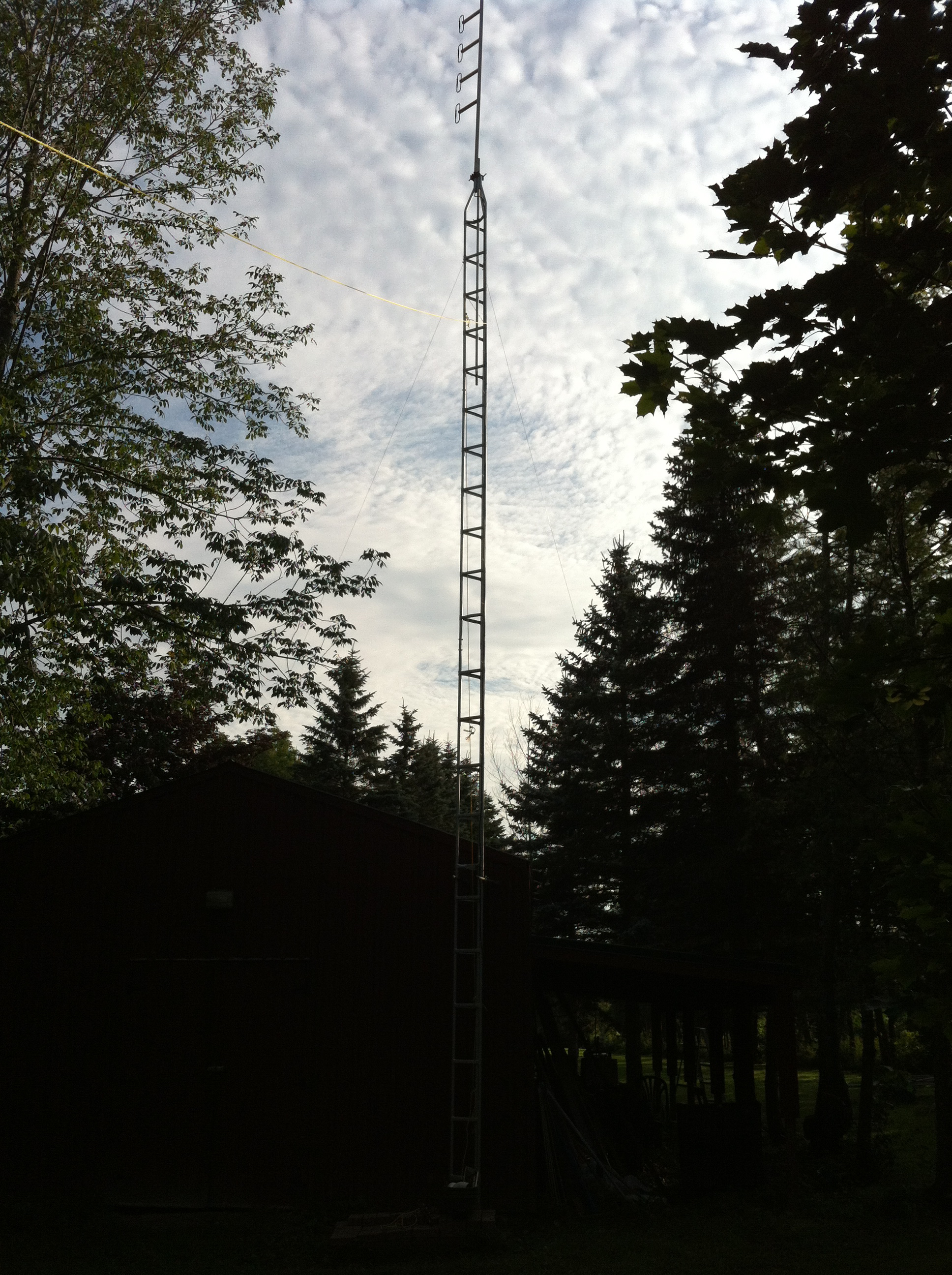
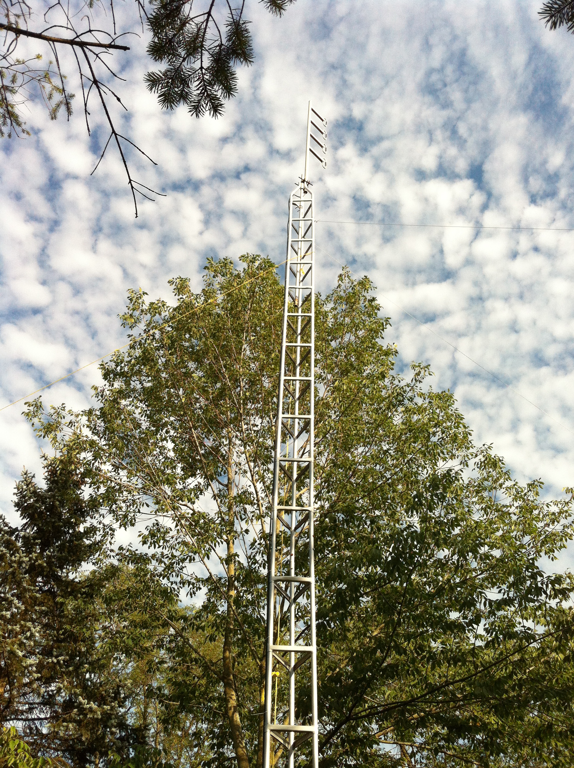
Eventually I was able to spruce up the TV Tower,, gave it a good brushing and a quality coat of aluminum paint. Added the 4-bay dipole antenna and a 50′ piece of LMR-400 coax cable (all assembled on the ground). Then I had my strong niece’s husband over for a beer and some antenna raising. Quite a job to pushup something like this. We managed, I tied it down with guy wires and house brackets.
The next day Bruce came over and he connected the coax cable and plugged the repeater in the power receptacle, and voila, that was all there was to it. The 4-bay dipole points toward the SW at 240 degrees (from Elora). Testing the system was easy, Bruce who lives in Fergus is at the back of the dipole and yet can hear the repeater very well. However directly south (toward Guelph) is not very good. We asked Terry and he tried and tried even with 50 watts and we could not hear him. Too bad.
When I drive from my place on 8th Line onto Hwy 86 I can trigger the repeater with ease, however getting near the Ariss Vally Golf Club, it is getting spotty. I tried in Kitchener and it work well with my 5 watt hand held. However close to the south west of Kitchener (shopping mall) I lost the signal, I am sure that a portable radio would have no problem. It also works well in Elmira, St. Jacobs, etc. So please give it a try.
Frequency: 442.950 Plus 5 Mz offset
Tone: 131.8
September 30, 2013
I removed the 4-bay commercial antenna and installed a 440 vertical that I used for field day. It is a shorty of around 5′. After climbing up a wobbly 40′ TV tower, I managed to remove the heavy 4-bay antenna and lowered it down without accident, except where it took some skin away. I then installed a vertical only to find out that the supplied u-bolts are for a 1 1/4″ pipe, whereas the tower has a 1′ pipe. Meaning that the supplied u-bolts are not threaded deep enough to tighten it up. So now the antenna is sitting loose on the pipe but the coax cable holds it down. Now I need to climb up there again.
In any case, the directional radiation has of improved but not enough to be heard in Guelph. It is still possible to raise the tower pipe by another 10′ or so, this might improve things even more.