Crown Antenna

The idea of the crown antenna came from the UK. Mr. Carl Mason GW0VSW, developed the idea and Dennis VE3UTN used a modified version of it during last year’s field day. It was a smallish affair and the height was around 2′ and 6′ despite the small area Dennis used it successfully in digital mode. I believe that Dennis received close to 80 contacts. The drawing below is showing Carls’ attic version. The high peaks are at the gable ends and the low peaks are along long end of the house.
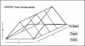
GW0VSW, CROWN wire loop antenna

In order to experiment further with this type of antenna a new one was setup at Johan VA3JBO. This time the crown antenna was vastly expanded, it measures 68′ by 34′ (20.7 m by 10.3 m) and the low points are 2′ (0.6 m) of the ground and the high points are 12′ (3.66 m) of the ground. The total wire length is close to 245′ (74.7 m). The antenna is corner fed using a 4:1 balun and the coax cable used is a piece of LMR400 of 120′ (36.6 m) in length. The radio used is a Yaesu FT897D. Contacts were made to Washington state and Georgia during a recent contest. Both stations reported 5 over 9.

Friday, September 27. Three members came out Al VA3TET, Bruce VA3QB and Dennis VE3UTN were present and brought with them the field day radio (since this is a tried and true transceiver they felt more comfortable using it). Again several contacts were made as far away as Germany. This fellow came booming in as he was using 500 watts. After trying for several more hours it became apparent that the something had to be done to improve the radiating qualities of this antenna.

Saturday, September 28. Well Friday became Saturday and Dennis made a few more contacts. After some fruitless hours Dennis changed the feed point from the corner to the center of the long end (the antenna was fed from the north/east corner and is now moved to the south/east center). It apparently made some difference but not enough. Dennis was of course disappointed with the results (and he may not like it that I am telling) but he asked me to remove the pictures, however I believe that they should stay as this is what experimenting is all about. In the end they will tell a complete story.

Remarks. The next step is to square up the antenna so that we have equal sides of peaks and valleys. Meaning a 68′ by 68′ square.

Tuesday, October  01. Changed the rectangle configuration to a square one. We now have an equal number of peaks and valleys on each side. Each section of angled wire measures 20′ in length and there are 16 sections, thus a total of 320′ of wire.  I know that one side of the square is 2′ short due to my deck being there. For those mathematically inclined we have actually only 318′ of wire.

We now have to wait for radio to be back here and then we can continue testing. The loop is still center fed. So can change one more parameter (connecting to a corner) and then I guess we are at the end of our song.

Wednesday, October 02. Reconnected the balun and connected the antenna to the transceiver. Not much going on around 14:00 – 15:00, tried again at 17:30 and got a hold of someone in Sao Paulo, he repeated my call sign but then conditions worsened and could not get him back. Pity. Again at 19:00 and the airwaves were full with American stations, could not get a word in edgewise.
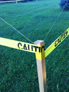
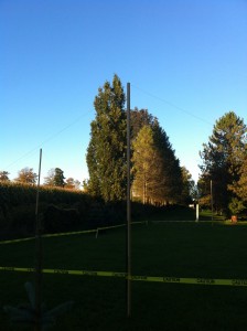
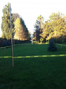
The low point of the crown antenna is 2' of the ground

The valley is 2′ of the ground


The peak is 12' of the ground

The peak is 12′ of the ground

The area is: 4624 sq. ft.
Length: xxx, Width: xxx

All four sides now 68′


Tower Climbing Safety Gear

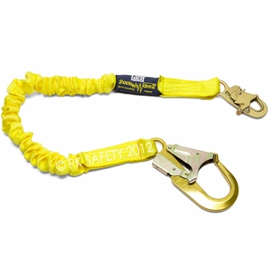
I was recently present at an antenna and tower take down. I observed that the people climbing the tower were using a “Shockwave Lanyard” as a safety rope. This is a dangerous procedure. The shockwave lanyard is a folded up and sewn together lanyard. If one falls of a tower the thread is meant to break thus slowing the fall of the climber. If this lanyard is used as a safety rope it is conceivable that the stitching may give away and the climber will find himself “falling” away from the tower.

Shockwave Lanyard

Shockwave Lanyard

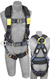
The lanyard above is clipped to the large D-Ring at the back of the harness. The lanyard below is clipped to the rings on either side of the belt.

Safety Harness

Safety Harness

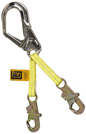
The lanyard below is a safety working rope. The large clip is clipped to the leg of the tower and the two smaller clips are clipped into the safety belt.

Safety Webbing Lanyard

Safety Webbing Lanyard


Cell Phone Tower Locator

This is an interesting web site. It will show you where cell phone towers are located and who owns the tower. This might be good information if or when moving into a new area.

http://www.ertyu.org/steven_nikkel/cancellsites.html


Elora Repeater

Elora Repeater Tower 1

Elora Repeater Tower 1


Elora Repeater Tower 2

Elora Repeater Tower 2

Just for fun we setup a second repeater at my place in Elora. Bruce still had his repeater at his house and wasn’t doing anything. I had a 40′ tower laying around and I also had the ERC Club dipole antenna stored here. So we figured why not combine the whole lot and see what we can do with it.

Eventually I was able to spruce up the TV Tower,, gave it a good brushing and a quality coat of aluminum paint. Added the 4-bay dipole antenna and a 50′ piece of LMR-400 coax cable (all assembled on the ground). Then I had my strong niece’s husband over for a beer and some antenna raising. Quite a job to pushup something like this. We managed, I tied it down with guy wires and house brackets.

The next day Bruce came over and he connected the coax cable and plugged the repeater in the power receptacle, and voila, that was all there was to it. The 4-bay dipole points toward the SW at 240 degrees (from Elora). Testing the system was easy, Bruce who lives in Fergus is at the back of the dipole and yet can hear the repeater very well. However directly south (toward Guelph) is not very good. We asked Terry and he tried and tried even with 50 watts and we could not hear him. Too bad.

When I drive from my place on 8th Line onto Hwy 86 I can trigger the repeater with ease, however getting near the Ariss Vally Golf Club, it is getting spotty. I tried in Kitchener and it work well with my 5 watt hand held. However close to the south west of Kitchener (shopping mall) I lost the signal, I am sure that a portable radio would have no problem. It also works well in Elmira, St. Jacobs, etc. So please give it a try.

Frequency: 442.950 Plus 5 Mz offset
Tone: 131.8

September 30, 2013

I removed the 4-bay commercial antenna and installed a 440 vertical that I used for field day. It is a shorty of around 5′. After climbing up a wobbly 40′ TV tower, I managed to remove the heavy 4-bay antenna and lowered it down without accident, except where it took some skin away. I then installed a vertical only to find out that the supplied u-bolts are for a 1 1/4″ pipe, whereas the tower has a 1′ pipe. Meaning that the supplied u-bolts are not threaded deep enough to tighten it up. So now the antenna is sitting loose on the pipe but the coax cable holds it down. Now I need to climb up there again.

In any case, the directional radiation has of improved but not enough to be heard in Guelph. It is still possible to raise the tower pipe by another 10′ or so, this might improve things even more.